Fuel system
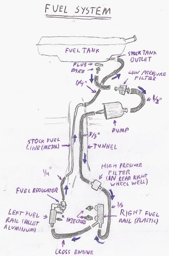
One of the bigger challenges of the system is the fuel system. The original fuel system, for the carburetor, was a one-way trip, a single line from the tank (which is at the front of the car, in the “trunk”) running through the main chassis tunnel from the fuel tank to the mechanical fuel pump on the engine, which fed the carburetor. The new system uses an electric pump, able to provide much more pressure and higher flow rate, mounted as close to the fuel tank as possible. Modern cars have it mounted inside the tank, but as this is a retrofit that wasn't feasible. From there fuel is pumped to the engine, runs through both fuel, rails, then through a pressure regulator that allows excess fuel not released by the injectors – the pump pumps much more fuel than the engine can consume, and fuel flows continuously – to flow back into the tank while regulating the pressure upstream. The pressure is kept at four bar (43 PSI) above the air inlet manifold pressure, which varies with throttle setting, this way the pressure across – and flow rate through – the injectors is consistent regardless of manifold pressure. This circuit system requires that there be two lines between the fuel tank and engine, and several new components be mounted. I decided to use the original fuel line as the low-pressure return line (as it is smaller than the new supply line, and wasn't intended to hold high pressures) and install a new supply system - I've heard of many others doing it this way.
A new hose barb as added to the tank, which was done by drilling and tapping a hole in an inspection plug on the bottom of the tank that a hose barb could thread into. Unfortunately I didn't think to take photos of this part before the tank was re-installed in the car. Fuel flows down from this through a large-diameter (1/2” ID) hose through a low-pressure filter, then into the pump. There are two filters, a low-pressure filter upstream of the pump and a high-pressure one between pump and injectors. The low pressure filter is to block any large debris from entering the pump, which is especially important as this new tank outlet is on the very bottom of the tank, so any sediment will drop into the line. The high-pressure filter is much finer, as even very fine particles can foul the tiny nozzles on the injectors. These hoses upstream of the pump go through some tight bends, and there were some problems of them pinching off and fuel not reaching the pump, starving the engine of fuel. This was eventually solved by inserting small coil springs inside the hoses to hold it open, much like a stent. The pump, which was included in the main box of parts, is a centrifugal-type electric pump, Bosch 0 580 254 957. The pump is mounted beneath the fuel tank immediately forward of the passenger footwell, attached using an exhaust hanger bracket from an auto parts store, bolted to the bulkhead below the fuel tank. When fuel was first added to the system, the pump leaked very badly, even unpressurized, but over the next several hours stopped leaking entirely, even while running, and has given no trouble since. Most likely the pump had sat unused several years, during which the seals and gaskets shriveled, when soaked in gasoline again they swelled and provided a good seal again.
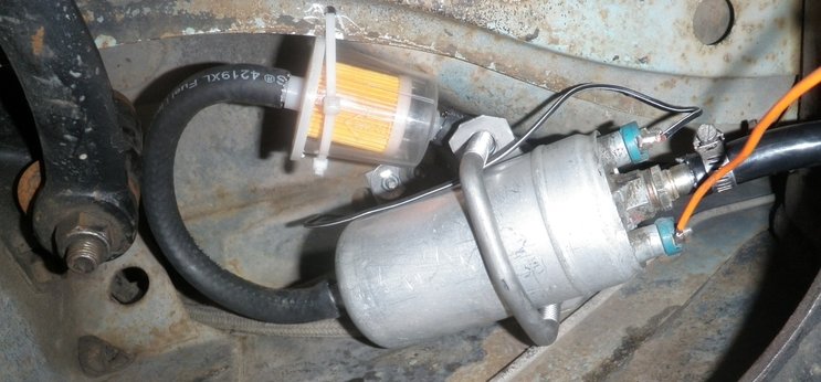
The low pressure fuel filter and pump. Fuel comes in from the tank above, through the filter (flowing right to left in this photo) through the curved hose into the pump, then from the pump into the tunnel. The curved hose tended to pinch off, so small coil springs were inserted in it as a stent. This is in the area in front of the passenger-side footwell, the arm to the left is the steering idler arm. The view is facing rear, the left side of the photo is the right side of the car. Photo taken before fuel was initially added, hose clamps were later added at all connections.
From the pump, the fuel runs through a flexible hose to the back of the car via the central tunnel, entering and exiting through holes drilled in the side of the tunnel - drilling these holes was quite a task. Metal hard-line may have been preferred, and cheaper, but I decided to use flexible hose for the entire length because it's much easier to install. Even with this, installing it was quite a hassle, performed by sliding a coat hanger in through the gearshift hole to catch a string, which was then used to pull the hose through. The hose emerges from the tunnel immediately forward of the transaxle, from there it is zip-tied to the transaxle supports and frame as it runs toward the right rear wheel well. In the right rear wheel well is the fuel filter, part number F777DL, the specified part for a modern “New Beetle,” held in place by a large hose clamp.
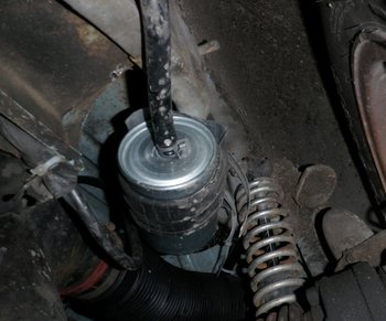
High pressure fuel filter, mounted in the wheel well. Easiest accessed with the wheel removed (this was the best photo I could get with it on, I'll get a better photo next time I take the wheel off.)
|
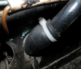
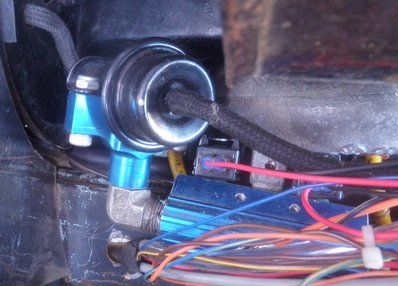
Fuel hose entry into engine bay, via one of the existing holes on the right side. Hose is wrapped in bicycle inner tube to prevent chafing due to engine movement.
|
Another hose then runs into the engine compartment, hooked to the right fuel rail. These fuel rails both supply fuel to the injectors as well as hold them in place physically. The right fuel rail is the stock Mexican part. From there the fuel passes through another hose across the engine to the right fuel rail. The right fuel rail is an aftermarket billet-aluminum part. The connections on the fuel filter and right fuel rail are the spring-clamp type, a bunch of which came with the fuel injection parts, apparently stock on the Mexican system, which seem to be plenty secure on these fittings. The left fuel rail has a brass barb, and a screw-type hose clamp - originally I used one of these spring-type clamps, it popped off and sprayed fuel straight at the spark plugs - had the engine been running at the time this car, and the house attached to the garage it was in, likely would no longer exist. Always be careful! The fuel regulator is attached directly to the right fuel rail with a metal elbow. From the fuel regulator, a smaller hose carries fuel to the stock fuel line through the tunnel, which emerges near the tank, where another hose returns it to what was originally the tank outlet.
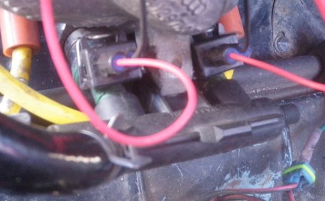
Right (Cylinders #1/#2) fuel rail, with hoses connected. The injectors are underneath the plug connections. Heavy yellow wires are spark plug leads.
|
Left (#3/#4) fuel rail, with attached regulator. Bundle of wires on top run to ECU. Cloth braded hoses are fuel return line (left, leading through tin) and manifold vacuum (right). The fuel return line is pressed against the hole firmly, so no relative motion occurs, and no chafing has been observed.
|
